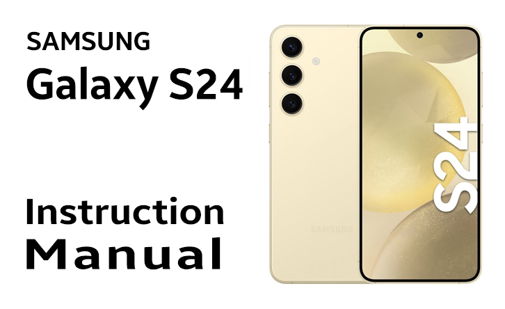
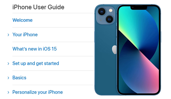
The Samsung Galaxy S24 is a powerful and versatile smartphone that offers a wide range of features and capabilities. To make the most of your device and ensure optimal performance, it’s essential to familiarize yourself with its settings and functions. This guide will provide you with an overview of how to download the Samsung Galaxy S24 instruction manual and explain why reading it is crucial for your device’s success.
How to download the Samsung Galaxy S24 instruction manual
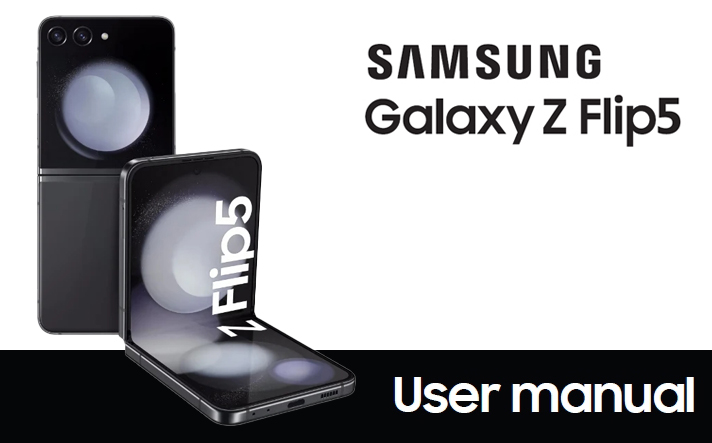
Downloading the instruction manual for your Samsung Galaxy S24 is a straightforward process. You can find the manual online through the following steps:
- Visit the Samsung website or your device’s carrier website.
- Locate the Samsung Galaxy S24 instruction manual page.
- Download the manual in your preferred format (e.g., PDF, HTML, or mobile app).
Alternatively, you can try searching for the manual on popular third-party websites like galaxys24manual.com or galaxys24userguide.com. These websites offer a wide range of instruction manuals for various devices, including the Samsung Galaxy S24.
Why you need to read the Samsung Galaxy S24 manual
Reading the instruction manual for Galaxy S24 offers several benefits that can enhance your device’s performance and user experience:
- It helps you understand the device’s features and functions, allowing you to make the most of its capabilities.
- It provides guidance on how to use the device’s settings and menus, ensuring a smooth and efficient user experience.
- It explains troubleshooting steps for common issues, helping you resolve problems quickly and prevent potential damage to your device.
- It keeps your device updated with the latest software updates and security patches, ensuring optimal performance and protection.
Benefits of reading the Galaxy S24 user guide
Reading the Galaxy S24 user guide can save you time and frustration by:
- Saving you from guessing and ensuring you’re using your device correctly.
- Preventing accidental damage to your device due to incorrect handling or usage.
- Helping you identify and resolve issues quickly, reducing the need for professional assistance.
- Enhance your overall user experience by making the most of your device’s features and capabilities.
Troubleshooting Common Issues
While the Samsung Galaxy S24 is generally a reliable device, it may experience some common issues that can be resolved by following the guidance provided in the instruction manual. Some of these issues include:
- Frequent crashes or unresponsiveness: This could be due to insufficient memory or outdated software. The instruction manual provides steps to free up memory or update your device’s software.
- Poor battery performance: The manual offers tips on how to optimize battery usage, such as turning off unused features or adjusting display brightness.
- Unclear camera settings: The instruction manual explains how to use the camera’s various features, ensuring you capture high-quality images and videos.
- Connectivity issues: The manual provides guidance on troubleshooting connectivity problems, such as Bluetooth pairing or Wi-Fi connection errors.
Conclusion
In conclusion, downloading and reading the Samsung Galaxy S24 instruction manual is an essential step for getting the most out of your device. By understanding its features, functions, and troubleshooting steps, you can ensure optimal performance and a smooth user experience. Don’t hesitate to consult the instruction manual for guidance on any aspect of your device’s usage.
